
Orbit Trap Properties Page
The Fractal Science Kit fractal generator Orbit Trap page holds a set of properties specific to Mandelbrot fractals and is visible only if the Process Orbit Trap property on the Mandelbrot / Julia / Newton page is set to Generate Data or Activate Controllers.
See also:
The following pages are found in the page hierarchy under the Orbit Trap page:
As each orbit point is computed, it is passed to the set of orbit traps to determine how close the orbit point is to each trap. However, the orbit point is not passed directly. Rather, it is first passed to several programs that can transform the point prior to passing it to the set of orbit traps. Manipulating these programs can result in significantly different images, yielding countless variations for a given set of traps.
First, the orbit point P is transformed by Transformation 1. When a point P is transformed, it is understood that P is passed through the transformation and the resulting transformed point placed back in P.
Next P is passed to the Symmetry Transformation. A Symmetry Transformation takes a single input point P and transforms it into 0 or more points. Let the resulting set of N points be called P[N]. Each of the N points in P[N] is now passed to Transformation 2.
Any or all of these transformations can be set to the identity transformation, thereby skipping that step. In fact, it is usually the case that most (or all) of these transformations are the identity transformation. However, selective use of these transformations along with other orbit trap properties can result in highly unusual and varied images even from the same set of orbit traps.
Up until now, we have not called any of the orbit traps! At this point we take each of the N points in P[N], and pass it to each of the M traps defined by Orbit Trap Map, resulting in at most N*M trapped points, the actual number depending on the defined transformations, orbit traps, and other orbit trap related property settings. Next, remember that the Orbit Trap Orbit Generation section of the Mandelbrot / Julia / Newton page defines several properties that control when (on which dwells) orbit trap processing takes place. If the number of dwells is K, then we can have at most N*M*K trapped points for a given orbit (usually far less). At the end of each orbit, we sort the set of trapped points based on the orbit trap Method property and use the sorted list to initialize the sample data passed to the controllers. If Orbit Opacity On is true (checked) we call the controllers for each of the trapped points (in the sorted order) until the room in the sample is exhausted. Otherwise, if Orbit Opacity On is false, we simply fill the sample based on the 1st element in the sorted list.
Orbit Trap Map defines the set of orbit traps and the properties used to map the trapped points to the sample data.
The Controllers page lets you set the list of Orbit Trap Controllers used to process this fractal. The Controllers page is visible only if the Process Orbit Trap property on the Mandelbrot / Julia / Newton page is set to Activate Controllers. The Controllers page is hidden if the property is set to Generate Data since the Classic Controllers are expected to process trapped samples in that case.
Orbit Trap
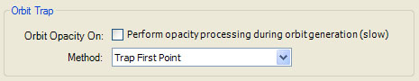
The Orbit Trap section holds 2 properties: Orbit Opacity On and Method. Method determines the ordering used when a point is trapped on multiple dwells. Method is set to one of the following values:
- Trap First Point
- Trap Last Point
- Trap Closest Point
- Trap Matching Point
- Trap Points Using Dwell Pattern
Remember that during the fractal orbit we keep statistics related to how close the orbit points come to the orbit traps. If more than 1 point within a given orbit is trapped, we need to determine which point's data is retained. Method solves this problem. If Method is Trap First Point, the point with the lowest dwell is selected. If Method is Trap Last Point, the point with the highest dwell is selected. If Method is Trap Closest Point, the point that is closest to the trap is selected. If Method is Trap Matching Point, the point that matches the criteria given in the Match Criteria section is selected. If Method is Trap Points Using Dwell Pattern, the Dwell Pattern section is used to define a permutation of the set of all possible dwell values, and the point whose dwell is closest to the top of the list is selected.
The Method controls the perceived order of the traps. Trap First Point places traps with lower dwells on top of those with higher dwells. Trap Last Point places traps with higher dwells on top of those with lower dwells. Trap Closest Point merges all traps together into a single object. The last 2 settings give finer control over the order and are explained below.
Orbit Opacity On turns on opacity processing across dwells. Normally, traps that fall behind other traps based on the selected Method are obscured by the trapped point. However, if the trapped point's color (set by the controller) has an Alpha value (opacity) less than 1, it should be possible to see through the point to those trapped points behind the trapped point resulting in a translucent trap. Of course, this has several major performance implications. We need to order the points based on Method, but process all the orbit points that are trapped, not just the first point we find. This also means we need to call the controllers during sample generation to process each of the trapped points. This negates several of the optimizations we normally perform (e.g., Solid Guessing) and increases the processing inside the fractal iteration which is the most expensive part of the fractal generation process. Clearly, this is necessary only if the controllers return colors with Alpha values less than 1 and should be disabled in all other cases. In fact, even if you require this processing, it is beneficial to leave Orbit Opacity On unchecked until you are ready to generate the final image.
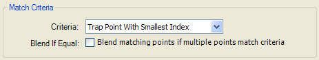
Match Criteria
When Method is Trap Matching Point, the Match Criteria section defines the criteria used to order the traps.
This section allows you to control the order of the traps based on the Trap Index or Trap Delta data values associated with each trap. The Orbit Trap Map page defines the Trap Index Map and Trap Delta Map properties that determine what data is mapped to the Color Controllers sample data fields Sample.TrapIndex and Sample.TrapDelta, respectively. These data fields are also used if you set the Method to Trap Matching Point to define the criteria used to order the set of trapped points.
The Criteria property is set to one of the following values:
- Trap Point With Smallest Index
- Trap Point With Smallest Delta
- Trap Point With Largest Index
- Trap Point With Largest Delta
Trap Point With Smallest Index sorts the trapped points from low to high based on the value of the Trap Index. The other settings access the Trap Delta field instead of the Trap Index field and/or sort from high to low rather than from low to high. Using one of these settings, you can control the order of the traps using logic in your Orbit Trap program. Simply set the trap's Index/Delta fields to order the traps as required.
The Blend If Equal property controls what happens if multiple points have the same index/delta value. If Blend If Equal is not checked, the point with the lowest dwell is selected and appears on top of the other traps. If Blend If Equal is checked, the point that is closest to the trap is selected which has the effect of blending all the traps with the given index/dwell together into a single object.
Dwell Pattern
When Method is Trap Points Using Dwell Pattern, the Dwell Pattern section defines a permutation of the set of all possible dwell values, and the point whose dwell is closest to the top of the list is selected.
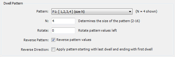
Normally, the traps are ordered within an image based on their dwell value. Traps with low dwell values will appear to be above traps with higher dwell values. The properties in this section allow you to define a pattern used to alter the order of the traps. The pattern is an ordered list of integers from 1 to S, where S is the size of the pattern. The list defines the perceived order of traps with dwell values between 1 and S. That is, a trap with dwell value equal to the 1st entry of the pattern would appear above all others. A trap with dwell value equal to the 2nd entry of the pattern would appear just below the 1st, and so on. Next you add S to each of the pattern elements to define an ordering on the next set of S dwell values (dwells S+1 to 2*S). This process continues until the entire set of traps has been reordered.
For example, the pattern [2,1]applied to the dwell values [1,2,3,4,5,6] would result in the list [2,1,4,3,6,5], effectively reversing every pair of values. The pattern [1,3,2,4] applied to the dwell values [1,2,3,4,5,6,7,8] would result in the list [1,3,2,4,5,7,6,8].
The Pattern property is set to one of the following values:
- P1: [ 1,2,3,4 ] (size N)
- P2: [ 1,5,2,6,3,7,4,8 ] (size 2N)
- P3: [ 5,1,6,2,7,3,8,4 ] (size 2N)
- P4: [ 1,8,2,7,3,6,4,5 ] (size 2N)
- P5: [ 8,1,7,2,6,3,5,4 ] (size 2N)
- P6: [ 1,3,5,7,2,4,6,8 ] (size 2N)
These are the 6 supported patterns. The property N controls the size of the pattern. The size is either N (for pattern P1) or 2N for the rest of the patterns. The pattern values given in the Pattern property text correspond to N equal to 4. As you increase N, the complexity of the image increases as more of the higher dwells become visible. N should be an integer between 2 and 16 inclusive.
The properties Rotate, Reverse Pattern, and Reverse Direction are used to alter the selected pattern. Rotate shifts the pattern to the left by Rotate elements. Numbers that fall off the left side of the pattern are added back into the pattern on the right. Rotate is an integer between 0 and S-1, where S is the size of the pattern (2N in most cases). Reverse Pattern reverses the pattern. Reverse Pattern is checked by default so that the larger traps are pushed down in the order and the smaller traps are displayed on top yielding a more interesting image. Reverse Direction applies the pattern starting with the last dwell and ending with the first dwell.
Surface Normal (Trap Value)
The Surface Normal (Trap Value) section controls the surface normal vector calculation based on the orbit trap value. The surface normal vector is used in the 3D Mapping section of both the Classic Controllers properties page and the Orbit Trap Controllers properties page, to support a 3D lighting model based on the orbit trap value.
The surface normal vector at each point is based on the orbit trap value at the point in conjunction with values at 2 adjacent points. These 3 values are taken as heights on the surface defined by the complex plane. The properties in this section control the selection and processing of these points/values.
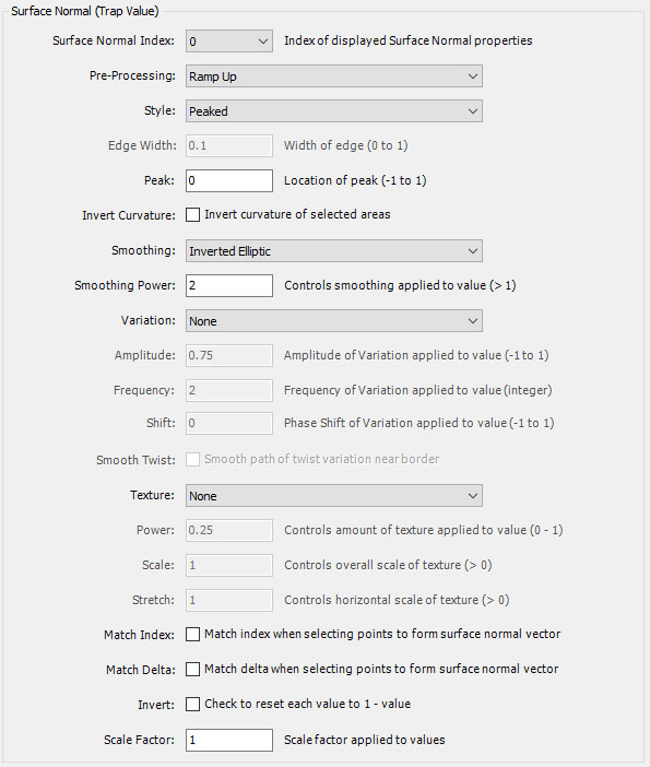
The Surface Normal Index dropdown controls which set of surface normal properties are displayed for edit in the remainder of the section. There are 4 sets of properties given by the index values 0 to 3, respectively. When you change the index, the properties associated with the new index are displayed in the remainder of the section so you can edit them as required. Each trap you define on the Orbit Trap Map page is mapped to one of the 4 sets of surface normal properties using the Surface Normal Index property given in the Selected Orbit Trap Properties section of that page.
The Pre-Processing property controls the initial surface normal processing.
The Pre-Processing property is set to one of the following values:
- Ramp Up
- Ramp Down
- Double Up
- Double Down
- Center Bounce
- Center Reflect
Normally, you can leave Pre-Processing set to Ramp Up (the default) but you can experiment with the other settings which add a level of complexity to the resulting traps. Ramp Up and Ramp Down are usually best for complex traps but the other settings can be interesting when dealing with simple traps.
The Style property is set to one of the following values:
- Flat
- Beveled
- Beveled Pair 1
- Beveled Pair 2
- Peaked
- Peaked Pair 1
- Peaked Pair 2
- Peaked Triple 1
- Peaked Triple 2
- Peaked Triple 3
- Peaked Triple 4
The Style property defines the style of the trap. The default is Peaked. Experiment with the other settings to change the way the trap is displayed.
The Flat, Beveled, and Peaked, settings are usually best for complex traps but the other settings can be interesting when dealing with simple traps.
The Edge Width, Peak, and Invert Curvature are related to the Style. Edge Width is controls the edge width of the beveled styles. Peak is the location of the location of the peak for the peaked styles. Setting Peak to 0 places the peak at the center of the trap. Setting Peak less than (greater than) 0, moves the peak towards the inside (outside) edge of the trap. Invert Curvature inverts the curvature of selected areas associated with the style, resulting in an alternate version of the style.
The Smoothing property is set to one of the following values:
- Linear
- Log
- Inverted Exp
- Root
- Inverted Power
- Inverted Elliptic
- Elliptic
- Power
- Inverted Root
- Exp
- Inverted Log
- Sigmoid
- Inverse Sigmoid
Smoothing and Smoothing Power control the smoothing function applied to the value. Setting Smoothing to Linear turns off smoothing. Normally, you will leave Smoothing at the default setting (Inverted Elliptic) but you can try the other settings to get different effects. Setting Smoothing to Elliptic, for example, inverts the orientation (concave/convex) of the trap smoothing. Increase/decrease Smoothing Power to increase/decrease the effect. Normally, a Smoothing Power of 2 is best.
The Variation property is set to one of the following values:
- None
- Twist 1
- Twist 2
- Twist 3
- Wave 1
- Wave 2
- Wave 3
Set Variation to one of the twist/wave settings to apply the selected variation to the trap.
Amplitude, Frequency, Shift, and Smooth Twist control the processing of the selected Variation. Frequency, Shift, and Smooth Twist apply to the twist variations, and Amplitude, Frequency, and Shift apply to the wave variations. Amplitude is the amplitude (given as a value between -1 and 1) of the wave. Frequency is an integer and controls the number of cycles of the twist/wave applied to the trap. Negative values reverse the direction of the twist/wave. Shift moves the origin of the twist/wave to a different position along the trap. Smooth Twist applies a smoothing function to the twist and can improve the resulting effect in some (but not all) cases.
The Texture property is set to one of the following values:
- None
- Striated
- Striated (Angled)
- Brushed
- Brushed (Angled)
- Speckled
- Stippled
- Hammered
- Rippled
- Wrinkled
Normally, you will not need to apply a texture to the trap but in selected cases it may add to the realism of the results. The default Texture is None and no texture is applied. Each of the other settings adds the named texture to the surface of the trap and enables the properties Power, Scale, and Stretch which add additional control over the resulting texture. Increase/decrease each property to increase/decrease the texture effect (Power), size relative to the trap (Scale), and/or aspect ratio (Stretch), respectively.
Match Index is a Boolean that, when checked, ensures the Orbit Trap Index for the 2 adjacent points match that of the associated point. This can sometimes be used to remove lines in the image at the transition between different areas of the trap.
Match Delta is a Boolean that, when checked, ensures the Orbit Trap Delta for the 2 adjacent points match that of the associated point. This can sometimes be used to remove lines in the image at the transition between different areas of the trap.
Invert is a Boolean that, when checked, resets each value to 1-value. This reverses the heights at each point; i.e., high points become low points and low points become high points.
Scale Factor is a value greater than 0 used to scale each value. Values greater than 1 amplify the associated heights, resulting in sharper peaks. Values less than 1 smooth the associated heights.
Normalization
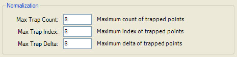
The Normalization section holds 3 properties: Max Trap Count, Max Trap Index, and Max Trap Delta. These values hold the maximum value across all trapped points for the sample data values Trap Count, Trap Index, and Trap Delta, respectively. They are required by the Orbit Trap Master Controller and the Orbit Trap Controllers to map the associated sample data to a normalized value between 0 and 1. Normally, these values are derived from the data after sample generation is complete. However, if Orbit Opacity On is checked, the controllers are invoked on the fly during sample generation so these values need to be set by you. The Normalization section is disabled unless Orbit Opacity On is checked. Of course, if your controller does not use the normalized values for Trap Count, Trap Index, or Trap Delta, these settings can be ignored.