
<Back> 1 2 3 4 5 6 7 8 9 <Next>
This tutorial creates several Orbit Traps and explores different methods of displaying them.
In Part 1 of the tutorial, we are going to learn the basics of setting up an orbit trap.
Orbit Traps are programs that define a set of geometric objects located on the complex plane and that keep statistics related to how close the orbit points come to these objects. These statistics are available to the controllers to color the fractal. The term orbit trap (or simply trap) can refer to both the program that defines the geometric object and the object itself, depending on context.
An orbit trap is processed with respect to a Fractal Equation and a set of orbit parameters. The trap is transformed on each iteration by the Fractal Equation, resulting in numerous distorted copies of the original object. Each dwell (iteration) is associated with a single transformed copy of the trap which gets more unrecognizable as the dwell increases. The term orbit trap is also used for the transformed copy produced on a given dwell.
Execute the Reset to Defaults command on the File menu of the Fractal Window.
Open the Properties Window and select the Mandelbrot / Julia / Newton properties page:
General
Mandelbrot / Julia / Newton
Set Type to Orbit Trap in the Mandelbrot / Julia/ Newton section of the page.

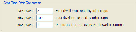
Examine the default settings for the Orbit Trap Orbit Generation section.
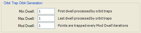
The Orbit Trap Orbit Generation section of the page defines several properties that control when (on which dwells) orbit trap processing takes place. Min Dwell is the 1st dwell to check for trapped points. Max Dwell is the last dwell to check for trapped points. Mod Dwell - 1 is the number of dwells to skip between checks. That is, a dwell is processed if the dwell is between MinDwell and MaxDwell inclusive, and (dwell - MinDwell) % ModDwell = 0. Min Dwell is used to skip points trapped on the earlier dwells which tend to obscure the later dwells. Max Dwell is used to limit the number of dwells where orbit trap processing is applied, usually for performance reasons. Mod Dwell is used to reduce the dwells where orbit trap processing is applied, usually to cull traps from a busy image.
The default value for both Min Dwell and Max Dwell is 1. This results in processing a single dwell and usually displays the base orbit trap alone on the page. There are two reasons I chose 1 as the default for Max Dwell. First, because some of the orbit traps are complex fractals in their own right (e.g., Kleinian Group, Schottky Group, Apollonian Gasket), they are best displayed outside the context of the Mandelbrot framework. Setting Max Dwell to 1 accomplishes this. Second, several of the orbit traps are very complex geometric objects and using a large value for Max Dwell would result in a fractal that would be too busy and take too long to process. It is best to display each orbit trap alone before you increase the number of iterations so you can get an idea how large or small to make Max Dwell. In addition, you can save some time by playing with the fractal properties when Max Dwell is low so the fractal generation time is fast. Once you find a set of properties resulting in an interesting image, you can increase Max Dwell as required.
Execute the Display Fractal command on the Tools menu of the Fractal Window to generate the fractal image.
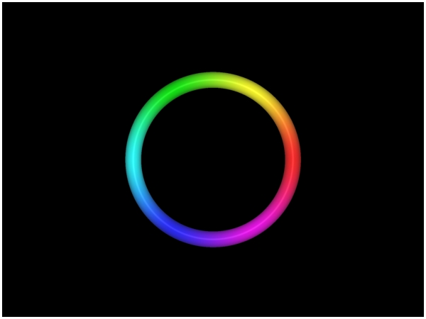
This is the default orbit trap (Circle) with respect to the dwell 1 of the built-in Fractal Equation Fractal Equation: Mandelbrot.
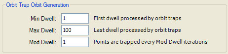
Set Max Dwell to 100.
Execute the Display Fractal command on the Tools menu of the Fractal Window to generate the fractal image.
This image displays the Circle trap with respect to the dwells 1 to 100 of the built-in Fractal Equation Fractal Equation: Mandelbrot.
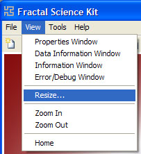
Now we need to zoom into the fractal. Normally, you would use the Zoom In box to interactively zoom into the fractal, but we will use the Set Image Viewport dialog so we will all be viewing exactly the same part of the complex plane. To view the dialog, execute the Resize command on the View menu of the Fractal Window.
The Set Image Viewport dialog lets you change the size of the fractal image and the location, size, and orientation, of the viewport onto the complex plane mapped to the image.
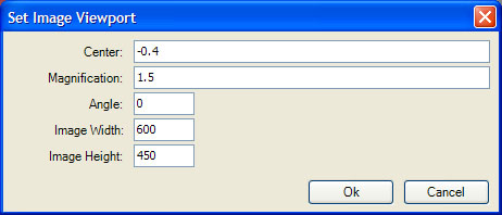
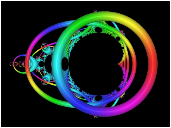
Set Center to -0.4 and Magnification to 1.5 and click Ok and wait while the application generates the sample data and processes the fractal image shown below.
Next, set Min Dwell to 2.
Execute the Display Fractal command on the Tools menu of the Fractal Window to generate the fractal image.

As you can see, by changing Min Dwell from 1 to 2 we have eliminated the 1st and topmost trap.
Set Min Dwell to 3 to eliminate the 1st and 2nd traps. By increasing Min Dwell, you can peal off any number of traps from the top and expose traps associated with the higher dwells. Typically, you will increase Min Dwell when you want to examine the traps on the higher dwells. Otherwise, the traps on lower dwells tend to dominate the image. Set Mod Dwell to 2 to display only the traps associated with every other dwell, or set Mod Dwell to 3 to display the traps associated with every 3rd dwell, etc.
Another way to view traps on higher dwells is to reverse the order the traps are displayed; i.e., display the traps with higher dwells on top of traps with lower dwells. We will see how to do that shortly.
Reset Min Dwell to 1, Max Dwell to 100, and Mod Dwell to 1.
Next, select the Orbit Trap properties page:
General
Mandelbrot / Julia / Newton
Orbit Trap
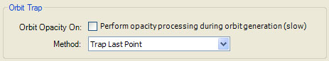
Examine the default setting for Method in the Orbit Trap section.

Method determines the ordering used when a point is trapped on multiple dwells. Method is set to one of the following values:
- Trap First Point
- Trap Last Point
- Trap Closest Point
- Trap Matching Point
- Trap Points Using Dwell Pattern
Remember that during the fractal orbit we keep statistics related to how close the orbit points come to the orbit traps. If more than 1 point within a given orbit is trapped, we need to determine which point's data is retained. Method solves this problem. If Method is Trap First Point, the point with the lowest dwell is selected. If Method is Trap Last Point, the point with the highest dwell is selected. If Method is Trap Closest Point, the point that is closest to the trap is selected. If Method is Trap Matching Point, the point that matches the criteria given in the Match Criteria section is selected. If Method is Trap Points Using Dwell Pattern, the Dwell Pattern section is used to define a permutation of the set of all possible dwell values, and the point whose dwell is closest to the top of the list is selected.
The Method controls the perceived order of the traps. Trap First Point places traps with lower dwells on top of those with higher dwells. Trap Last Point places traps with higher dwells on top of those with lower dwells. Trap Closest Point merges all traps together into a single object. The last 2 settings are advanced features not covered by this tutorial.
Let's look at some examples.
Execute the Display Fractal command on the Tools menu of the Fractal Window to generate the fractal image.
This is the result of the default setting Trap First Point. As you can see, the traps associated with lower dwells are foremost in the image.
Set Method to Trap Last Point.
Execute the Display Fractal command on the Tools menu of the Fractal Window to generate the fractal image.
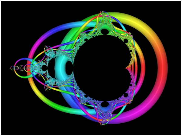
Now, the traps associated with higher dwells are foremost in the image.
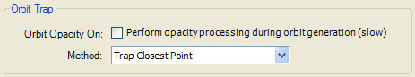
Set Method to Trap Closest Point.
Execute the Display Fractal command on the Tools menu of the Fractal Window to generate the fractal image.

Now, all the traps have been merged together.